

1.Construction of the STATIC TRANSFER SWITCH
General Topology:-
The STS system is composed of INPUT(A) switch, INPUT(B) switch, INPUT(A) fuse, INPUT(B) fuse, BYPASS(A) breaker, BYPASS(B) breaker input filter & MOV, INPUT(A) static switch, INPUT(B) static switch & the OUTPUT switch. The basic topology is shown in the diagram above.
Under normal condition, both INPUT(A) switch, INPUT(B) switch & OUTPUT switch should be closed, the BYPASS(A) breaker, BYPASS(B) should be opened, when both AC power A & B are normal, that is within the preset voltage & frequency range, then the default static switch will be conducting & supply power to the output load.
When one of the AC power has problem, either go out the preset voltage or frequency range, or even completely no power, the STS can detect it in a fraction of milli-second, if this happen at the default AC source, and the other AC source is normal, then the default static switch will turn off, and the second source static switch will turn on to supply the load from the second source, these transfer is done by CPU, therefore the total time elapsed from power failure to power recover measured at the output is 2~3ms, therefore the load will not be interrupted.
When the default source recover back to normal range, then the load will transfer back to the default AC source after 3~4 second without interruption or no voltage dip.
2.Main properties and characteristics
AST TRANSFER (TYPICAL) : 1.5~2ms(0 deg diff.),
2~6ms(<90deg diff.).
GEOMETRICAL INCREASE IN OUTPUT AVAILABILITY.
COMPACT SIZE : 44cm X 44cm X 55cm (W X H X D).
LIGHT WEIGHT : 24 ~ 30 kg
HIGH EFFICIENCY >99%
EASY INSTALLATION : Rack Mount & Terminal Blocks..
EASY START-UP : Use Switch Button.
FAST REPAIR : Plug & Play Power Module.
QUIET OPERATION : <50dBA
INPUT PHASE DIFFERENCE ACCEPTIBLE.
SINGLE/THREE PHASE SELECTIBLE.
VOLTAGE RANGE +/-5,10,15,20% SELECTIBLE.
FREQUENCY RANGE +/-0.5,1.0,1.5,2.0,2.5 Hz SELECTIBLE.
SENSITIVITY LO/MED/HI SELECTIBLE.
BREAK BEFORE MAKE TRANSFER SEQUENCY
MANUAL/AUTOMATIC TRANSFER SELECTIBLE.
MANUAL/AUTOMATIC RETURN SELECTIBLE.
MANUAL BYPASS USE BREAKERS (With Inter-lock).
ACCEPT HARSH ENVIRONMENT.
CUSTOMER DESIGN UP TO 1000A.
3.Geometrical increase in output availability
The availability of AC power at output can be calculated:
1 - (1 - source A availability) * (1 - source B availability)
If source A availability = 0.95, source B availability = 0.9, then you will get 0.995 availability at the output.
4.Dimensions & Drawings
5.The Control Panel:
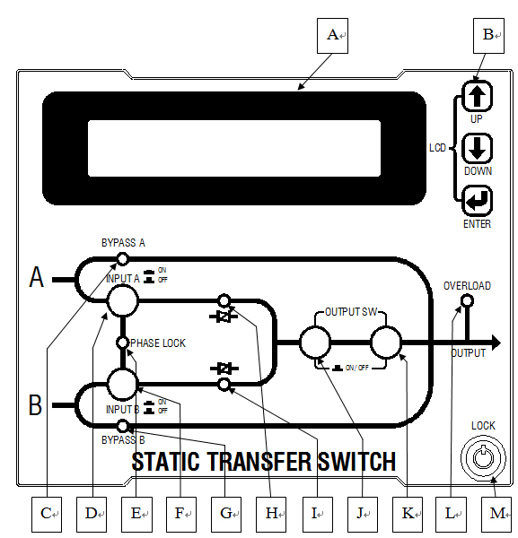
A: LCD display- Real time status, data or historical events is displayed on the LCD. The STS parameters, real time clock, transfer setting, buzzer also can be set through this LCD. The LCD is back lighted by LEDs for purpose of a sharp display, but in order to lengthen the LED’s life time, the LED will be automatically shut off 3 minute after no key is activated, will light up again when one of the up/down/enter key is pushed.
B: LCD up/down/enter control button.
C: Bypass A LED: This LED will lit when the maintenance bypass A breaker is closed. When the maintenance bypass breaker is closed, the STS will stay at the bypass source, will not transfer by any other conditions.
D: INPUT A switch & LED: It is a push button switch with latch, will close the input A switch when this button is pressed. LED will lit when the input switch close is closed, and AC power is normal
E: Phase lock LED: this LED will lit when input A & input B are locked in phase within the range set in the LCD, 5,10,15,20,** deg.
F: INPUT B switch & LED: It is a push button switch with latch, will close the input B switch when this button is pressed. LED will lit when the input switch close is closed, and AC power is normal.
G: Bypass B LED: This LED will lit when the maintenance bypass B breaker is closed. When the maintenance bypass breaker is closed, the STS will stay at the bypass source, will not transfer by any other conditions.
H: A static switch LED: This LED will lit when the INPUT A static switch is turned on and the INPUT B static switch is turned off. Both LED should never lit simultaneously.
I: B static switch LED: This LED will lit when the INPUT B static switch is turned on and the INPUT A static switch is turned off. Both LED should never lit simultaneously.
J & K: Output switch: When both button is pressed at the same time, can turn on the output switch. To turn off the output switch is the same, press both button at the same time.
L: Overload LED: Will lit when the output is overloaded.
M: Lock: Unlock with the attached key can open the front panel, access to the bypass breaker, power module & PCB inside.
6.Fast Maintenance:
Power module is plug and play when the door is opened, pull out and plug a new one.

TYPICAL TRANSFER WAVEFORM WITH 0 DEG PHASE DIFF. HI SENSITIVITY:-
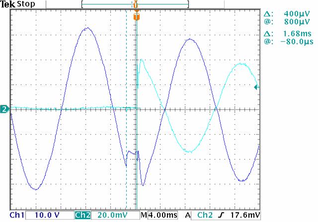
TYPICAL TRANSFER WAVEFORM WITH 45 DEG PHASE DIFF. HI SENSITIVITY:-


 闽ICP备14002031号-2 版权 © 2014朗臣科技版权所有